LAMRS Equipment, Installation of a Wired DCC decoder in an Athearn "Blue Box" loco
[ GIRR Home ] [ LAMRS Equipment Home ] [ Previous ] [ Next ]
Installation of a Wired DCC decoder in an Athearn "Blue Box" loco.
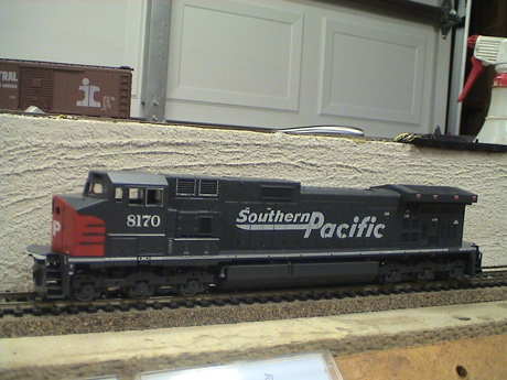 I found a box stock Athearn "blue box" loco at the club. It was clearly marked as donated LAMRS property. This kind of loco was the low cost Athearn product. It is pretty basic and was designed and probably built at about the same time NMRA DCC became standardized in 1993. Due to the loco's age, there is no provision for a plug in DCC installation.
The prototype, a GE C44-9W, was only made between 1993 and 1996. The "C" means 3 powered axles per truck, the "44" means 4400 hp, the "-9" described the vintage of the electronics and the "W" was for a wide cab.
This particular model has very low miles from the appearance of the wheels and commutator. The detail parts were never installed but there is a bag of detail stuff (which I have not opened) in the original box.
The club may or may not elect to keep this loco, but since it was completely stock and it ran well on DC, I elected to do a photo study of the conversion of this very common older loco to DCC using a club owned test decoder. Much of the same techniques used to convert this loco can be applied to other makes and models of DC locos that were designed and built before DCC became common.
Digitrax makes a kit for installing a decoder into this kind of loco, a DH163AT. It allows a solder free installation, but the work is not a lot different from what is described below. All in all, the kit is not worth the extra $3 or so that it costs as all the parts that are needed are already in the loco.
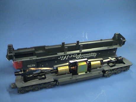 There is not much inside a blue box loco besides a motor and a headlight. Many of them don't even have the headlight. The shell on this one is held on by four clips that poke through slots in the fuel tank. To remove the shell, remove the couplers and work the clips from the bottom with a flat blade screwdriver. The clips will release and the shell can be pulled off.
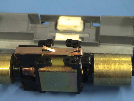
 The "wiring" consists of metal clips attached to the motor. A long clip reaches forward and aft to contact metal brackets that come up from each truck. This contact is on the engineer's side on all Athearn blue box locos.
The contact between the power pickup clip and the trucks has been a reliability problem and this clip is usually the first thing to go to be replaced with a wire soldered between the risers and the top motor contact.
The bottom motor contact reaches down with some spring fingers to contact the frame which is connected to the fireman's side power pickups via a metal plate on each truck on which the loco frame rests.
 The headlight is connected via a spring clip to the power pickup clip. The other side of the headlight contacts it's mounting bracket which leads back to the frame.
Most of the headlight parts will be scrapped. In this loco, the light shield was retained.
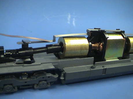
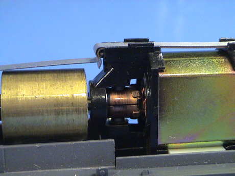 The motor is a partial open frame design. The magnet and field piece are a fairly modern design, but the brushes are exposed. They are also replaceable. The brushes are held against the commutator by springs that reside under the upper and lower motor clips. When these clips are removed, be sure that the clip is removed slowly and restrained so that the brush spring doesn't launch itself into the wild blue yonder. DO NOT attempt to solder to the motor clips while they are attached to the motor. The soldering heat will likely melt the plastic motor frame. The top and bottom clips also hold the motor together so when you take them off, remove only one at a time.
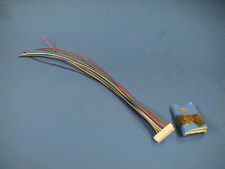 I had just one HO decoder left, a club owned DH121 that came to the club in the Blue Goose. It has a failed headlight function as whoever installed it in the Blue Goose did it improperly and didn't isolate the headlight from the frame. The harness is a standard 7" wired harness with a JST connector that fits the decoder. This harness is left over from some previous club installation that didn't need the harness that came with a new decoder.
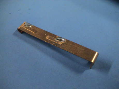
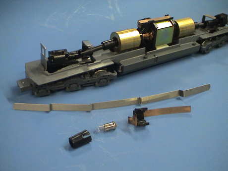 Other than the headlight bezel, these parts will be scrapped. The long contact clip cannot be used and isn't wanted. The headlight and it's mounting features are useless too because the headlight cannot be allowed to contact the frame.
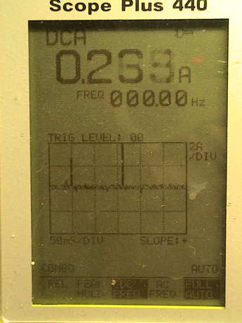 I tested the motor on a bench power supply and found that the motor current is fine at 250 mA or so. However, the motor does draw some commutation spikes. These are fairly normal, at about 4 amps peak. The decoder can handle these. If the spikes were much larger, I'd add a current limiting resistor of 3 to 5 Ω in series with the motor. There is a small amount of sparking at the commutator but it is not serious and not even unexpected. Many motors spark a little at the commutator including can motors.
 When the motor is removed, the fingers that provide contact to the frame are revealed. The VERY MOST IMPORTANT part of a DCC installation is to isolate the motor from all other wiring. I do this by making a small modification to the lower clip.
The lower clip has two fingers that have been die cut away from the clip body. Be careful when removing this clip from the motor so that you don't lose the brush spring that it retains. It also holds the motor together so don't remove the upper clip until you replace this clip.
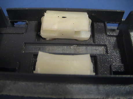 The motor is held to the frame in soft plastic pads. I was able to just pull the motor right out. The lower clip contacts rest in the slot between the pads and contact the frame base metal in the slot.
 There are a number of ways to get rid of the spring fingers. One is to clip them off, another is to press them back into the slots. On this one, I pressed them back in but they clearly didn't want to stay so I attached a dab of solder to each to hold them out of the way.
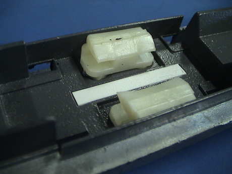 Just dealing with the spring contacts is enough to isolate the motor, but if you are a belt and suspenders type, you can attach a piece of 0.020" by 0.125" styrene back into the slot with CA.
 While the clips are removed from the motor solder the orange and gray motor wires to the clips. The gray wire attaches to the bottom clip.
One easy way to determine which motor wire to solder to which motor terminal is to note what the wiring was before the motor wiring was modified. The motor terminal that eventually goes to the rail on the engineer's side is the key. That side of the power pickups get the red wire and the orange wire (similar to the color red) goes back on that motor terminal. The same thing holds for the other side. The black and gray wires are similarly colored. The black wire goes to the rail on the fireman's side and the gray wire goes to the motor terminal that was connected to the fireman's side rail.
On all Athearn locos that I have come across, the frame is connected to the fireman's (left) side rail.
 Sometimes these mounts will come out with the motor, sometimes they stay with the frame. When it is time to reinstall the motor, it is much easier to do it if one of the mounts is removed. Work around the stud end on the bottom of the loco and force the stud back into the hole in the frame. Then push out the mount. Slip the motor back into the remaining mount and then put the removed mount back onto the motor and push the whole works back into the frame. The commutator end of the motor goes forward.
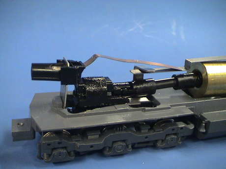
 The black decoder wire (left rail) goes to some point on the frame. I soldered it to the headlight bracket. The red decoder wires goes to the right rail, it is soldered to the top of the riser from the front truck
 I actually cut the red wire near the decoder and attached the red wire from the front truck to the back truck and them also attached the short red wire that goes to the decoder socket to the riser on the rear truck. The decoder itself will eventually be held in place with a cable tie so that it sits just aft of the rear riser and above the rear gear tower.
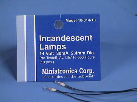 The club supplied some Grain Of Wheat bulbs. I used the 14 volt 30 mA version. At the club track voltage of about 13.5 volts, there will be just 12 volts available to drive the headlight. Running a 14 volt bulb at 12 volts extends it's life significantly and reduces the heat it produces so that it won't melt nearby plastic parts.
If a bulb draws more than 80 mA or so, it may need a inrush current limiting resistor to protect the decoder. Incandescent bulbs draw more current when they are cold. They heat rapidly and then the current reaches spec. However, for a fraction of a second they can draw enough to damage some decoders. It is recommended that higher current bulbs be wired in series with a 22Ω resistor to limit the inrush to safe levels. The 30 mA bulbs used here do not need this resistor.
Incandescent bulbs are not polarity sensitive.
Headlights can also be made with white or warm white LEDs. However LEDs are polarity sensitive AND they require a current limiting resistor. A value of 470Ω is suitable for HO track voltages if you want a really bright headlight that draws the full 20 mA that a typical LED is rated at. A 1KΩ resistor reduces the current to about 10 mA and still results in a very bright headlight. The longer lead of the LED is the positive lead. If you have clipped the leads, then you can also tell by looking into the clear plastic lens from the side. The smaller electrode is the positive one.
If you would like to read more details about using LEDs for lighting, then look at my White LED Tips page.
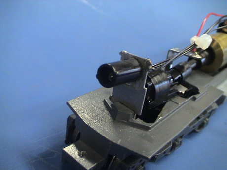 I reused the light shield for the front headlight by attaching it back to the headlight bracket with gel CA. Then I simply pushed one bulb back into the light shield to mount it.
The mounting of headlights in a loco that didn't have them or, like in this case where the existing light is scrapped, is an issue. You would like the headlight physically mounted to the frame so that there are no wires between the frame and the shell. In this case I was able to reuse the mounting feature for the front headlight. I could have built a bracket at the rear to mount the rear headlight to the frame too but instead I choose to simply use gel CA to attach it's wires to the rear of the shell to hold the bulb in place.
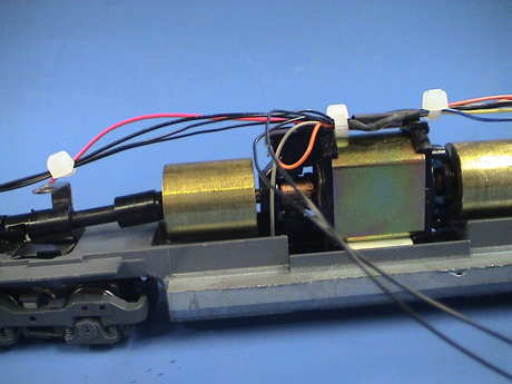 The wiring harness needs to be kept from rubbing on a flywheel. This becomes obvious by the noise that is made when there is rubbing. A cable tie holds the headlight wires and the black and red decoder wires up against the front truck riser. Two more hold the bundle which now included the motor wires and the rear headlight wires to the top of the motor and away from the rear flywheel.
The headlight wiring to the decoder is straightforward. The decoder blue wire supplies a constant positive voltage at about 2 volts less than the track voltage. One lead of both bulbs is connected to the blue wire. The other lead of the front headlight connects to the decoder white wire. The other lead of the rear headlight connects to the yellow wire.
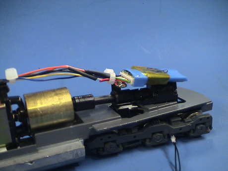 The decoder itself is tied to the rear truck wire because the red wires are soldered to the rear riser and it is an easy way to loosely tie the decoder down. The decoder body just rests on the rear gear tower. The rear headlight bulb not attached in this photo, but it was eventually attached to the rear of the shell with a drop of gel CA.
Before a loco with a newly installed decoder is placed on powered track, it should be tested on a programming track. Try reading back CV1 (the 2 digit address) to see if the value is correct, 03 for a new or recently reset decoder. If the installation was done incorrectly in such a way that the decoder might be damaged (non isolated motor or lights), the decoder will respond with an error. A Digitrax throttle will display no-d or maybe 255 or some other unexpected message. Wiring errors should be identified and fixed before proceeding.
If the decoder is responsive, it is a good plan to set CV29 to 2 (turn off analog conversion) and write the address for the loco. Successful programming is an indication of a safe install. If you choose to use a 4 digit address, set CV29 to 34.
If the loco runs backwards from what the throttle indicates that it should, then the motor wires are reversed. There are ways around this with programming, but it is usually better just to fix the wiring by reversing the orange and gray wires at the motor.
Once the loco has had a road test and passed, then the shell can be reattached, the decoder further programmed as desired and it is good to go.
[ GIRR Home ] [ LAMRS Equipment Home ] [ Previous ] [ Next ]
This page has been accessed  times since Dec 2, 2010.
© 2010-2011 George Schreyer
Created 2 Dec 10
Last Updated February 16, 2011