 18 Dec 08
 19 May 07 12 Oct 08
The information presented below is substantially based on ONE PRE-PRODUCTION C-16 so that some of the things that I observed may be particular to this individual unit. The paint scheme on this unit differs from the "production" paint scheme that I saw at the 1999 Big Train Show at the Queen Mary.
18 Dec 08 19 May 07 12 Oct 08The C-16 is a small steam loco commonly called a Consolidation type, or 2-8-0. The C-16 class itself was pretty much exclusively used on the D&RG in their early days, but the Consolidation type was used everywhere in great numbers through the last part of the 19th century. Even into the 20th Century, the Consolidation type continued to be built, but generally in larger configurations than the C-16. With some minor detail work, the Aristo C-16 could pass for a PRR Class H1 type, or a narrow gauge version of many other kinds of Consolidations that ran all over the country.
This model is a remake of the original Delton C-16. Aristo purchased the molds and the model, according to Aristo, should look very similar to the Delton product in most aspects, including most proportions. Aristo has entirely rebuilt the mechanism as the original Delton mechanism had a nasty reputation for poor performance and reliability. The major change is that the gearbox is now dicast metal and the first and fourth drivers are driven by gearing. The gearbox was also designed so that "daylight" still shows under the boiler forward of the firebox. Unfortunately, there wasn't room for adequate gearing so the engine body was raised by 1/4" to make room. This made the model deviate from the exact proportions of a real C-16. Finescalers are outraged by this change, but in this case the reality of product design outweighed finescale concerns. However, this "problem" can be fixed with a little bashing on the model, see Lowering the C-16 below.
Aristo paints and details the engines in various schemes, some as coal burners, some as wood burners. Details such as stacks, marker lights, pilots, compressors, air tanks, dynamos, headlights, domes and such will vary from model to model.
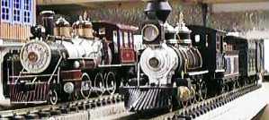
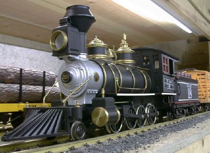
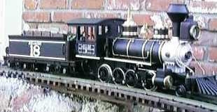 The ATSF model pictured is a wood burner which is
representative of a Baldwin or Grant catalog engine. It has a very long
pilot, a diamond stack to catch cinders, fluted domes, a single stage
air compressor, a kerosene headlight (therefore no dynamo either) and
no marker lights. This is a pre-production unit and Aristo says that
the paint scheme will be "fixed" on production units although I don't
see much wrong with it from a general point of view. I have no photos
of a very early ATSF 2-8-0 to check the "accuracy" of the paint scheme.
The scheme does not represent engines that were painted 50 years later,
but things could have changed in half a century. The engine is numbered
18 on the engine and tender body, but has a number of 268 on the
smokebox door.
The ATSF model pictured is a wood burner which is
representative of a Baldwin or Grant catalog engine. It has a very long
pilot, a diamond stack to catch cinders, fluted domes, a single stage
air compressor, a kerosene headlight (therefore no dynamo either) and
no marker lights. This is a pre-production unit and Aristo says that
the paint scheme will be "fixed" on production units although I don't
see much wrong with it from a general point of view. I have no photos
of a very early ATSF 2-8-0 to check the "accuracy" of the paint scheme.
The scheme does not represent engines that were painted 50 years later,
but things could have changed in half a century. The engine is numbered
18 on the engine and tender body, but has a number of 268 on the
smokebox door.
Most of the gold colored details including the pops, whistle, headlight bezel, domes caps, cylinder heads and such on the wood burner are turned brass parts. The handrails and piping are brass rod. The bell is painted dicast metal. The connecting rods are plastic.
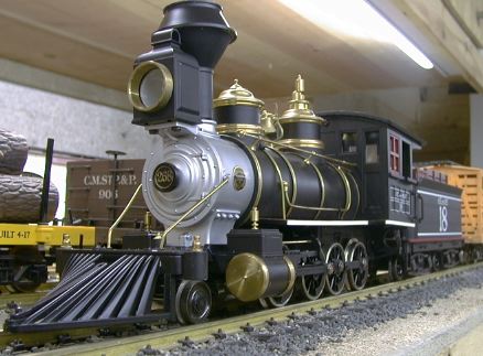
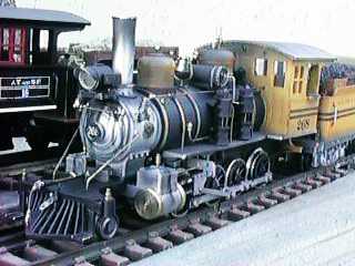 The Denver and Rio Grand Western model pictured here
is a more modern coal burner that represents the real C-16 type. The
pilot is shorter, it has an electric headlight and a dynamo, non-fluted
domes and dual air compressors. Please note that this is also a
pre-production model. Further Mac McCalla has already had at this one.
Mac has lightly (by his usual standards) weathered it and some of the
details that were on the original model have been moved, modified or
changed out entirely.
The Denver and Rio Grand Western model pictured here
is a more modern coal burner that represents the real C-16 type. The
pilot is shorter, it has an electric headlight and a dynamo, non-fluted
domes and dual air compressors. Please note that this is also a
pre-production model. Further Mac McCalla has already had at this one.
Mac has lightly (by his usual standards) weathered it and some of the
details that were on the original model have been moved, modified or
changed out entirely.
[Top]
The ATSF Aristo C-16 that I evaluated runs very well and pulls strongly. It handled 12 heavy cars with metal wheels on a 1.6% grade. See my Tractive Effort Tests page for the details. This engine pulls the most cars for the least current of any engine that I have come across so far so it would be a good candidate for battery power. In testing on the indoor GIRR, Mountain Division, it would handle 8 cars with metal wheels on a 4.2% curving grade and 4 cars in a 5.2% 4' diameter spiral.
The center two drivers are blind (no flange). This not only aids in getting through tight curves, it is prototypical as the real C-16's had blind drivers. Unlike the Aristo Pacific and 0-4-0, the driver axles are not allowed to rock with respect to one another. This will tend to make the engine more sensitive to poorly leveled track, but it also allows the engine to slip gracefully when overloaded. The Aristo Pacific and 0-4-0 hop about and complain loudly when they start to slip.
There was some gear noise at first, but it quieted down considerably in only a few minutes of running and then continued at the "light whine" level. The engine runs smoothly at low speed, although it takes a little higher track voltage to start moving than a Bachmann Shay. This is not a fast engine, it more closely matches the speed of the Shay than any of the other Aristo engines. I was successful in double heading the C-16 and the Shay. At speeds up to about 15 smph (the fastest that a real Shay would go) it matches the speed of the Shay quite closely. At 18 volts, I estimate that the C-16 runs at about 30 smph, about the top speed of a real C-16.
After a week, I've had the opportunity to put some hours on the engine. I estimate that I've got about 20 hours on it so far, with about half of those under maximum load. Under extended running with all the cars it will pull on the grades of the outdoor GIRR (12 cars in that case) the gearbox got warm but the engine showed no signs of stress.
The engine is already fairly heavily weighted so that I imagine that there is not much room in the boiler for anything else. The tender is small too so fitting it with onboard batteries would be a challenge. However since the engine only draws a little over an amp with a maximum practical load, a small battery set may work.
The engine is equipped with a smoke unit, and in typical Aristo fashion, it smokes for quite a while, but not real strongly. There is a three position toggle switch on the backhead which allows the engine to run with the motor, lights and smoke, with just the lights and the motor or with lights only. There does not appear to be a way to turn the lights off although this may be a pre-production problem as the instructions indicate that the lights should go off. The engine is not equipped with a sound system but after market systems can easily be installed.
The headlight is bright and white and casts a good beam although it is not directional. There is also a light in the firebox, but it does not flicker. I do not know if the models with markers have illuminated markers.
I laid some 2' radius track and turnouts on the family room floor to see how it would do. The bottom line is that it did fine. Even though it has a longer wheelbase, it doesn't complain in a 2' turn like an LGB Mogul. The engine is smaller than a Bachmann Big Hauler, so anywhere a Big Hauler will go, the C-16 will go too.
When I took the C-16 to the indoor GIRR, Mountain Division, it ran fine too and fit everywhere that the Big Hauler did. However, a couple of times the lead truck on the tender derailed. I suspected a problem with the drawbar, see the Problems section below for details.
The drawbar design is different that other Aristo locos and I think that it is generally better. Unlike the design on the Aristo Pacific (which is a major pain in the backside to connect or disconnect) it is easy to get the engine and tender connected, and when the drawbar finally latches under the tender, there is a reassuring click. I have had no difficulty with the drawbar separating, even under very heavy loads.
[Top]
I initially experienced no derailment problems on my outdoor track (which is not in the best condition courtesy of El Nino) although there was an easily correctable interference issue, see the Problems section below.
Later, when I was running with a heavy load on a little used section of track, I noticed a consistent derailment difficulty. As the engine exited a curve, it would consistently derail on a turnout. As turns out, the pony truck was derailing halfway through the curve and then kicking the engine off the track when the already derailed pony truck hit the turnout. I found that this section of track changed from a positive superelevation of about one bubble, to a negative superelevation of about a bubble, back to a positive superelevation of about a bubble, all within about one foot! This was too much for the engine to handle. When the track was set for a consistent superelevation, the engine had no more difficulties on this section.
However, running the other direction I began to have a problem on one spot that is under construction where the track is not adequately supported. Here, I found another systematic derailment difficulty. It is true that this is a pathological case, but this time I decided to see if I could make the engine more tolerant instead of fixing the track. I did find that a simple modification to the pony truck mount allowed the engine to pass this section without difficulty and without fixing the track (I'll get the track fixed later when I am finished with the roadbed in that stretch).
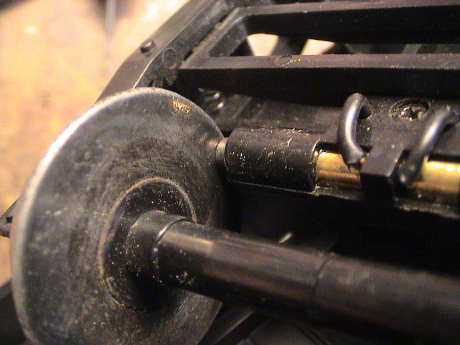
When the track changes in level abruptly, the engine body can tip and lift a pony truck wheel off the track. The pony truck can then move sideways and when it comes down, it can be off the track. The engine can actually run for quite a distance with the pony truck derailed without seeming to have a problem. I discovered by inspection that the vertical travel of the pony truck was limited by an interference between the truck pivot and the engine gearbox. This limits the ability of the pony truck to drop downward far enough to stay on badly leveled track.
 I ground off some
plastic from the rear of the pony truck pivot where it was binding
against the gearbox. This binding was fairly severe as the paint had
been rubbed off the metal gearbox at that location. I kept grinding and
fitting until light started to show through the plastic indicating that
I had removed nearly all of the plastic right at the top of the pivot.
I also reinstalled the pivot without tightening the mounting screw all
the way down. Now the pony truck has significantly more vertical play
and moves MUCH more freely AND the
engine will run by the especially bad track without the pony truck
wheels lifting at all and without derailing.
I ground off some
plastic from the rear of the pony truck pivot where it was binding
against the gearbox. This binding was fairly severe as the paint had
been rubbed off the metal gearbox at that location. I kept grinding and
fitting until light started to show through the plastic indicating that
I had removed nearly all of the plastic right at the top of the pivot.
I also reinstalled the pivot without tightening the mounting screw all
the way down. Now the pony truck has significantly more vertical play
and moves MUCH more freely AND the
engine will run by the especially bad track without the pony truck
wheels lifting at all and without derailing.
[Top]
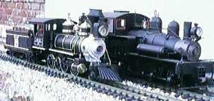 The C-16 is a fairly small
engine, built to 1/24 scale. 1/24 scale is not correct for the 3'
narrow gauge C-16 prototype (1/20.3 is the right scale) so the engine
will look a little small against other 1/20.3 scale equipment. Sitting
next to a 1/20.3 scale model of a 36 ton Shay, the C-16 is visibly
smaller. The 36 ton Shay is a small engine too, in real life they would
be about the same size.
The C-16 is a fairly small
engine, built to 1/24 scale. 1/24 scale is not correct for the 3'
narrow gauge C-16 prototype (1/20.3 is the right scale) so the engine
will look a little small against other 1/20.3 scale equipment. Sitting
next to a 1/20.3 scale model of a 36 ton Shay, the C-16 is visibly
smaller. The 36 ton Shay is a small engine too, in real life they would
be about the same size.
 Even sitting next to
a Bachmann Big Hauler the C-16 looks small. The boiler sits much lower
and the cab is lower too. The Ten Wheeler prototype was not a large
engine either, but it was intended for higher speeds and had taller
drivers. The C-16 was intended to haul freight at low speed and had
especially small drivers so that eight of them could fit under the
engine. However, compared to the Bachmann stock car behind the C-16,
the proportion is good.
Even sitting next to
a Bachmann Big Hauler the C-16 looks small. The boiler sits much lower
and the cab is lower too. The Ten Wheeler prototype was not a large
engine either, but it was intended for higher speeds and had taller
drivers. The C-16 was intended to haul freight at low speed and had
especially small drivers so that eight of them could fit under the
engine. However, compared to the Bachmann stock car behind the C-16,
the proportion is good.
I don't have a set of C-16 drawings so I couldn't check the engine for accuracy. If someone out there has access to some drawings, I'd like to get a copy so that I can measure the engine against them.
The wood burner C-16 with the diamond stack is 6-7/8" tall over the railheads, 4-1/2" wide over the cab roof and 25" long over the extended pilot to the rear of the tender deck. The worst outside overhang is at the rear corner of the cab roof at 2-7/8" from the track centerline on 2' radius track. The worst inside overhang is less than that of a typical boxcar. This is small enough so that it will probably fit on most layouts.
[Top]
Power is picked up on all eight drivers and four tender wheels. On my unit, one of the drivers on the third axle didn't pick up power, but this is not really a big deal because the blind drivers don't sit on the track all the time anyway. The pony truck has metal wheels but does not pick up power. There is a small electrical connector between the engine and tender that gave me some minor grief, see Problems below.
The drivers have plastic centers with metal tires. Power is transferred from the tires to the axle by a metal clip. On my unit, this clip was not making electrical contact to the tire even though it visually appears to be in contact. Sometime, if I ever have to take the driver off, I'll fix it.
The tender wheels have metal tires on plastic centers. Power is picked up on four tender wheels with low drag replaceable carbon brushes.
The C-16 seems to tolerate moderately dirty track gracefully and the engine wheels do not seem to load up with crud as I have experienced with other Aristo steamers. The tender wheels do seem to get dirty faster than the engine wheels. Even with intermittent power pickup, the motor seems to be able to keep spinning so that it can coast over bad track such that the gear whine pitch changes some but the engine doesn't sputter or jerk like some other locos.
While playing with a digital sound system installed in the tender, I noticed that the tender wheel power pickups seem to have fairly high and unstable resistance ranging from 20 to 200+ ohms per wheel. The excessive resistance appears to be located at the interface between the wheel and the brush itself. The contact brush resistance itself varies a little, but is usually on the order of 2 ohms or so. Burnishing the blackening off of the backs of the wheels did improve the situation, but it was not a complete solution. The lowest resistance came down to the sub 10 ohm range, but the contact resistance would still go to several tens of ohms at times.
After I installed DCC in the loco, I checked the tender wheels again. They were still flakey, and badly so. The contact resistance was in the hundreds to thousands of ohms, fully useless. I polished the backs of the wheels with a wire brush in a Dremel tool and it helped a little but not enough. Then I burnished the back with a Brite Boy and the resistance of that wheel dropped into the tens of ohms range, still not good, but better. Each of the other three responded the same way. There is still a major issue with the surface condition of the wheel backs.
However, when I run the DCC equipped engine with the track power disconnected, it now runs ok on the tender pickups alone as long as it is on clean track. There are only four wheels contributing to power pickup on the tender so that it cannot be expected to be tolerant of dirty track. However, power is at least now getting from the wheels to the tender body in some fashion where it wasn't before.
 A couple of
months later, I checked the tender wheel pickup again and it was bad
again. There is something about the stock wheels that seems to degrade
over time when it should not. The wheel backs appeared to be reasonably
clean, except for the dust, but they didn't work at all. The brush to
wheel contact resistance was all over the map from hundreds to
thousands of ohms. Clearly, something had to be done here.
A couple of
months later, I checked the tender wheel pickup again and it was bad
again. There is something about the stock wheels that seems to degrade
over time when it should not. The wheel backs appeared to be reasonably
clean, except for the dust, but they didn't work at all. The brush to
wheel contact resistance was all over the map from hundreds to
thousands of ohms. Clearly, something had to be done here.
 I changed out
the wheelsets to a set of Bachmann small wheels. These are 24.5 mm in
diameter, smaller than the stock wheels by a little, but they seem to
work better, at least when new. We'll have to see what the result is
over time.
I changed out
the wheelsets to a set of Bachmann small wheels. These are 24.5 mm in
diameter, smaller than the stock wheels by a little, but they seem to
work better, at least when new. We'll have to see what the result is
over time.
 The brushes
are positioned a little far out even with the stock wheels. Part of the
brush was never in contact with the wheel. With the Bachmann wheels,
2/3 of the brush was past the edge of the flange. I drilled a new hole
in the mounting tab for the brush holder and moved it inward a little.
This actually brought the brushes inward a little too much, but it was
good enough. The actual performance of the new wheels seemed to be
quite a bit better than the stock wheels even without a break in.
The brushes
are positioned a little far out even with the stock wheels. Part of the
brush was never in contact with the wheel. With the Bachmann wheels,
2/3 of the brush was past the edge of the flange. I drilled a new hole
in the mounting tab for the brush holder and moved it inward a little.
This actually brought the brushes inward a little too much, but it was
good enough. The actual performance of the new wheels seemed to be
quite a bit better than the stock wheels even without a break in.
 After a week of break in,
the Bachmann wheels seemed to be working somewhat better than the
Aristo wheels, but they still were not what I was expecting. I
installed my last two LGB contacts on a styrene strip on the rear most
wheelset. The strip and contacts are installed with Zap-A-Gap CA. The
wires were soldered on to the contacts first, then they were glued in
place. Then I tapped into the wires on the other axle to connect them.
Now the resistance is in line with my expectations. It will get down to
a few ohms. It still does vary upward into the 10's of ohms. The other
contacts are running ten times higher. The performance of the tender
alone was much better than before when on moderately dirty track. On
very clean track, the old contacts were still a little flakey. On
moderately dirty track, the old contacts were somewhat flakey and on
very dirty track they just didn't work because the wheels weren't
making sufficient contact to the track. WIth the 3rd axle added, the
performance on very dirty track was not changed much but the 3rd
wheelset seemed to be helping some. However, the performance on
moderately dirty and clean track was good.
After a week of break in,
the Bachmann wheels seemed to be working somewhat better than the
Aristo wheels, but they still were not what I was expecting. I
installed my last two LGB contacts on a styrene strip on the rear most
wheelset. The strip and contacts are installed with Zap-A-Gap CA. The
wires were soldered on to the contacts first, then they were glued in
place. Then I tapped into the wires on the other axle to connect them.
Now the resistance is in line with my expectations. It will get down to
a few ohms. It still does vary upward into the 10's of ohms. The other
contacts are running ten times higher. The performance of the tender
alone was much better than before when on moderately dirty track. On
very clean track, the old contacts were still a little flakey. On
moderately dirty track, the old contacts were somewhat flakey and on
very dirty track they just didn't work because the wheels weren't
making sufficient contact to the track. WIth the 3rd axle added, the
performance on very dirty track was not changed much but the 3rd
wheelset seemed to be helping some. However, the performance on
moderately dirty and clean track was good.
 It would appear that the basic problem is not the condition of the
wheel back, but on the contact itself not making a reliable connection
to a clean surface. I got some more LGB type contacts from Massoth. The
Aristo contact is the same size as the long LGB contact. The drill is
to solder a short wire on the end of the contact and slide it back into
the contact holder feeding the short wire out the hole at the end. Then
the short wire can be connected back to the tender.
It would appear that the basic problem is not the condition of the
wheel back, but on the contact itself not making a reliable connection
to a clean surface. I got some more LGB type contacts from Massoth. The
Aristo contact is the same size as the long LGB contact. The drill is
to solder a short wire on the end of the contact and slide it back into
the contact holder feeding the short wire out the hole at the end. Then
the short wire can be connected back to the tender.
By the time that I did this, I already had DCC in this loco. Power is normally jumpered between the loco and the tender so that the tender can help provide power to the loco. However, since my decoder is in the tender, the loco helps the tender power pickup. Before I changed the contacts, the loco essentially did not run on the tender contacts alone (jumper unplugged). After I had LGB (Massoth) contacts on 6 of 8 wheels on the tender, the loco ran fine using the tender pickup alone.
Eventually, I moved the Aristo wheels to a Bachmann Columbia tender to replace the Gary Raymond wheels that were there. The Gary Raymond wheels have a smaller flange and were just causing too many derailment problems. The Aristo wheels were almost the same size as the Gary Raymond wheels. The power pickup on the Columbia is now good so that the Aristo wheels themselves seem to be ok. The evidence indicates that the Aristo brushes were the problem all along.
[Top]
The power connector between the engine and tender is arranged to hang out the back of the engine. However, in backing moves, it tended to get dragged underneath the engine and hang up in turnouts. I rerouted the connector and wire through the drawbar slot and used a small cable tie to anchor it to the side of the drawbar and that problem went away.
The drawbar itself clips under the tender. Besides the fact that mine was broken out of the box (some Zap-CA fixed that in a hurry) the drawbar tends to lift the front of the tender off the track slightly. This didn't give me any derailment problems on the outdoor layout. However, indoors I got a couple of derailments of the leading tender truck so the drawbar was immediately suspect.
 The drawbar seems to be 1/8" too high at the tender
connection and it is also 1/8" thick. The fix was obvious. I broke the
glue joint in the middle of the drawbar and reglued the end of the
drawbar under the piece attached to the engine with a 1/4" overlap.
This both lowered the drawbar by 1/8" AND pulled the
tender closer to the engine by 1/4". In a 2' radius curve, the front
corner of the tender deck just misses the engine frame. With the
modified drawbar, the tender truck derailments ceased and I still had
no problems with the drawbar disconnecting by itself.
The drawbar seems to be 1/8" too high at the tender
connection and it is also 1/8" thick. The fix was obvious. I broke the
glue joint in the middle of the drawbar and reglued the end of the
drawbar under the piece attached to the engine with a 1/4" overlap.
This both lowered the drawbar by 1/8" AND pulled the
tender closer to the engine by 1/4". In a 2' radius curve, the front
corner of the tender deck just misses the engine frame. With the
modified drawbar, the tender truck derailments ceased and I still had
no problems with the drawbar disconnecting by itself.
[Top]
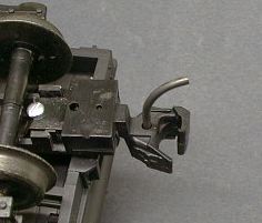
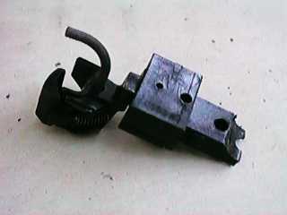
As soon as I started to test the pulling power of the engine, I ran into a problem. The stock Delton type coupler is mounted too low to couple with the Kadee "G" Scale couplers that I use on the GIRR. Since the engine is eventually going to the GIRR, Mountain Division which uses LGB knuckles, I just hacked on a Kadee for testing.
I used a Kadee #831 by grinding out the Delton type pivot post and mounting the Kadee body with a Kadee screw to a hole that was already in the coupler mount. There are two bumps on the side of the #831 body that need to be ground off to allow the body to fit. Even so, the coupler is a little low. Grinding off some more of the coupler body would fix that. The coupler works OK mounted this way, but the coupler sticks out too far.
 Cutting off some more of the coupler mount
allows an #831 body to be tucked back under the tender where it
belongs. I cut the side panels of the mount so that there was only
about 1/4" left and then filed the remaining mounting surface flat.
Cutting off some more of the coupler mount
allows an #831 body to be tucked back under the tender where it
belongs. I cut the side panels of the mount so that there was only
about 1/4" left and then filed the remaining mounting surface flat.
 The very end of the coupler body must be
ground down so that it will fit under the axle when the truck springs
are compressed.
The very end of the coupler body must be
ground down so that it will fit under the axle when the truck springs
are compressed.
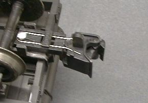 An LGB
knuckle coupler will mount the same way in the same hole that the
tucked in Kadee uses. It also mounts a little low, but the LGB knuckle
is very tolerant to incorrect mounting height. The end of the LGB
knuckle also needs to be ground down to fit under the axle.
An LGB
knuckle coupler will mount the same way in the same hole that the
tucked in Kadee uses. It also mounts a little low, but the LGB knuckle
is very tolerant to incorrect mounting height. The end of the LGB
knuckle also needs to be ground down to fit under the axle.
The pilot has too much overhang to reasonably expect a coupler to work there. The long pilot version has a nonfunctional drawbar on the pilot.
[Top]
David Fletcher provided a note on the LSOL and Aristo Bulletin boards with a description of how he lowered the C-16. It seemed the obvious way to do it and it turned out to be fairly easy. Virtually all of the modifications are done to the C-16 frame so it the conversion doesn't go well, another frame can be purchased and the engine returned to like new condition with one exception.
David's method is to hack at the frame such that the motor block recesses 1/4" higher into the frame. The mod does exactly what is necessary. The entire engine is lowered without significant impact on the air space between the frame and the boiler. There are some side effects, but they are minor.
 This is the C-16 before the
modification. Note how high the pilot is above the track and how the
pony truck has to reach down to the track. The centerline of the
cylinder should line up with the axle, but is instead 1/4" higher.
This is the C-16 before the
modification. Note how high the pilot is above the track and how the
pony truck has to reach down to the track. The centerline of the
cylinder should line up with the axle, but is instead 1/4" higher.
 After the modification, note that the
pilot rides right down by the track, the pony truck is nearly
horizontal and the cylinder centerline lines up with the axles. The
motor block does invade slightly into the air space between the frame
and the boiler, but only by about 1/16". The equalizer bars at the ends
of the springs are disconnected from the frame, but this doesn't show
much as they are hidden behind the wheels anyway.
After the modification, note that the
pilot rides right down by the track, the pony truck is nearly
horizontal and the cylinder centerline lines up with the axles. The
motor block does invade slightly into the air space between the frame
and the boiler, but only by about 1/16". The equalizer bars at the ends
of the springs are disconnected from the frame, but this doesn't show
much as they are hidden behind the wheels anyway.
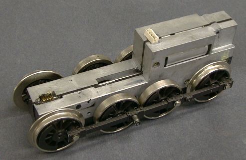 The C-16 motor
block is a metal cased piece. It needs to be removed to do the work,
but modification of the block is not required. The motor block attaches
to the loco with a 4 terminal connector. The two center pins go to the
motor, the outer pins to the power pickups. The block halves are
electrically connected to the power pickups so there is an insulator
between the case halves.
The C-16 motor
block is a metal cased piece. It needs to be removed to do the work,
but modification of the block is not required. The motor block attaches
to the loco with a 4 terminal connector. The two center pins go to the
motor, the outer pins to the power pickups. The block halves are
electrically connected to the power pickups so there is an insulator
between the case halves.
I checked mine and the motor and power pickup connections are isolated properly. However, there have been some reports that sometimes the motor is not isolated. I didn't tear into the block to look, but there might be cases of an unintended short between a motor terminal and a case half. If some future R/C or DCC installation is anticipated, this might be a good time to check it and fix it if there is a problem.
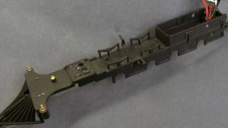 This is
the frame before any modifications. It has been stripped completely
down. To get to this point, the superstructure is removed from the top,
the motor block is pulled out of the bottom and the cylinder assembly
is disassembled and removed from around the frame.
This is
the frame before any modifications. It has been stripped completely
down. To get to this point, the superstructure is removed from the top,
the motor block is pulled out of the bottom and the cylinder assembly
is disassembled and removed from around the frame.
To strip the engine far enough to lower it, follow these steps. Your engine might be somewhat different as this unit is a pre-production model.
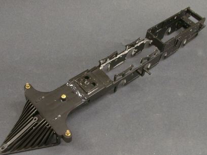 The
modification involves cutting and grinding on the frame and a couple of
other pieces to allow the motor block to recess 1/4" more deeply. The
bottom of the block will end up flush with the bottom of the frame.
The
modification involves cutting and grinding on the frame and a couple of
other pieces to allow the motor block to recess 1/4" more deeply. The
bottom of the block will end up flush with the bottom of the frame.
Cut out the flat part of the frame under the boiler and grind it flush to the sidewalls. Then grind the forward part of the firebox 1/4" higher. Then grind each of the 8 axle slots 1/4" deeper. Keep grinding and fitting until the motor block fits easily and is completely flush with the bottom of the frame.
The springs are a bit of a problem when the equalization rods are ground to clear the raised motor block, they will be disconnected from the frame. The springs will then be attached only by the central support of each spring. Be careful not to break off the equalization rods. David commented that he cut the spring assemblies completely off and reattached them further outward so that they would clear the block. He also moved them 2 mm forward to more closely align them with the axle positions.
A new hole must be drilled for the motor block mounting screws between the 3rd and 4th drivers. Drill a new hole 1/4" above the old one.
This picture was taken before the frame was repainted to cover all the evidence of the grinding. The lower top surface of the motor block will need painting as well because it will stick up a little under the boiler.
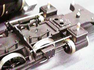 The center boiler saddle (the
flat piece crosswise to the frame) also supports the crosshead and
valve gear. This photo shows how it goes together before the
modification. Since the motor block will partially invade the space
that this part takes, it needs some relief ground in it to clear the
raised motor block. Eventually it fits back in right where it is
now.
The center boiler saddle (the
flat piece crosswise to the frame) also supports the crosshead and
valve gear. This photo shows how it goes together before the
modification. Since the motor block will partially invade the space
that this part takes, it needs some relief ground in it to clear the
raised motor block. Eventually it fits back in right where it is
now.
 There are also two bosses that stick out from
under the cab. These will have to be ground off so that the original
screw hole is completely gone or the bosses will interfere with the
raised motor block. This is the one modification that is not easily
reversible. David commented that he remanufactured new bosses that
mount further rearwards, but I elected just to abandon them. The clips
at the back seemed to be secure enough to hold the whole works
together.
There are also two bosses that stick out from
under the cab. These will have to be ground off so that the original
screw hole is completely gone or the bosses will interfere with the
raised motor block. This is the one modification that is not easily
reversible. David commented that he remanufactured new bosses that
mount further rearwards, but I elected just to abandon them. The clips
at the back seemed to be secure enough to hold the whole works
together.
David noted a problem with the length of the piston rods. He had to trim his. Mine didn't interfere with the cylinder head so I left them alone. The crosshead will now move right up next to the cylinder, but it clears.
With the engine sitting lower, there might be a problem with the pilot. Mine hung just a little too low, the tip was exactly at the rail height and tended to catch on uncouplers and such. The pilot support rods can be used for what they were intended, to support the pilot. Raise the pilot by hand and observe how much of the rod sticks through the pilot. Then remove the rod and bend the bottom end backwards about 15 degrees for the length that stuck out when the pilot was at the right height. The bent ends will bind below the hole and you can then hook the top ends back into the smoke box to hold the pilot up.
The lowered engine frame also lowers the drawbar. Depending how yours sits now it might need some adjustment. In my case with the modified offset bar, I had to turn it over to raise the tender end of the bar to an appropriate height.
[Top]
The C-16 uses a standard Aristo type plug in smoke unit. The unit generates light smoke for quite a while, but often the density of the smoke is so light that at all but the highest speeds, it is not visible.
LGB or Seuthe elements work much better. If you can find a Seuthe unit, its the same thing, but probably cheaper. I choose an 18 volt unit as the C-16 runs the smoke unit directly from the track. At prototypical speeds, the smoke unit gets about 14 volts which is just right. The smoke unit generates very visible smoke but doesn't consume fluid at an inordinate rate. It also dissipates only about 1.5 watts which also seems about right for long life of the element, even running dry.
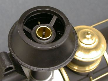 An LGB or
Seuthe smoke unit fits right into the wood burner's stack with no
modifications at all required to the loco. I do not know if the
production wood burner stack or the coal burner stack will be so
easy.
An LGB or
Seuthe smoke unit fits right into the wood burner's stack with no
modifications at all required to the loco. I do not know if the
production wood burner stack or the coal burner stack will be so
easy.
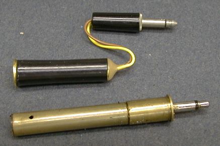 The stock smoke unit plugs into
the loco using a standard 3.5 mm miniature plug. All that is necessary
is to trim the wires of the smoke unit to about 2" and solder them to
the plug. The plug is then inserted into the loco and the wires are
allowed to coil around in the base of the stack. These plugs are
usually used for headphones and most will be set up for stereo with
three connections, tip, ring and sleeve (in telco-speak). This one is a
monaural version in that it does not have a "ring." Either kind will
work, but don't connect anything to the "ring" contact.
The stock smoke unit plugs into
the loco using a standard 3.5 mm miniature plug. All that is necessary
is to trim the wires of the smoke unit to about 2" and solder them to
the plug. The plug is then inserted into the loco and the wires are
allowed to coil around in the base of the stack. These plugs are
usually used for headphones and most will be set up for stereo with
three connections, tip, ring and sleeve (in telco-speak). This one is a
monaural version in that it does not have a "ring." Either kind will
work, but don't connect anything to the "ring" contact.
[Top]
The C-16 comes with a standard track powered, nondirectional incandescent headlight. It is fairly bright the way it is, but I elected to install a white LED in place of the bulb. More information on bright white LEDs can be found on my White LED Tips page.
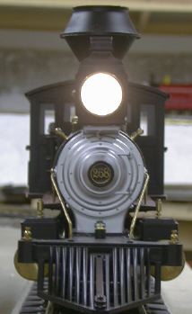
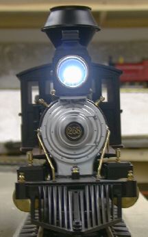
The photo on the left is the stock headlight. The one on the right is after the white LED installation. In the photo, the LED doesn't look that much brighter, but it does cast a much better beam. Its color is more suited to an electric light instead the of the oil light on this version of the model but I like the brightness.
 The circuit diagram for the LED installation
is very simple. A series resistor limits the current to the LED to
about 15 mA. The extra diode is not really necessary but I put it in
anyway. The LED is a diode itself so that it automatically provides
directional lighting. However, I found little data on how well these
LED's put up with reverse bias so I added the diode to prevent the LED
from avalanching. I did test it without the diode and it appeared to
work ok, no detectable current was drawn. When the motor is off, the
LED will be absolutely dark when the track polarity is reversed. With
the motor on, it LED will light dimly anyway. I assume that is because
there is commutator noise that spikes the track voltage just a little
positive, even going in reverse. If your LED lights brightly in reverse
instead of forward, reverse the power wiring to the whole circuit.
The circuit diagram for the LED installation
is very simple. A series resistor limits the current to the LED to
about 15 mA. The extra diode is not really necessary but I put it in
anyway. The LED is a diode itself so that it automatically provides
directional lighting. However, I found little data on how well these
LED's put up with reverse bias so I added the diode to prevent the LED
from avalanching. I did test it without the diode and it appeared to
work ok, no detectable current was drawn. When the motor is off, the
LED will be absolutely dark when the track polarity is reversed. With
the motor on, it LED will light dimly anyway. I assume that is because
there is commutator noise that spikes the track voltage just a little
positive, even going in reverse. If your LED lights brightly in reverse
instead of forward, reverse the power wiring to the whole circuit.
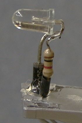 The physical installation in the C-16 is
very easy. The headlight housing can be removed with two screws. Mine
had a little bit of glue in there as well, but the headlight came off
with minimal force. The hole in the bottom of the housing is big enough
so that the LED can fit back through it. The diode and resistor mount
in series with the LED leads and support the LED. The whole works is
held in place with a dab of hot glue. The leads on the LED have to be
bent close to the housing to allow the LED to mount rearward enough so
that it doesn't interfere with the headlight lens.
The physical installation in the C-16 is
very easy. The headlight housing can be removed with two screws. Mine
had a little bit of glue in there as well, but the headlight came off
with minimal force. The hole in the bottom of the housing is big enough
so that the LED can fit back through it. The diode and resistor mount
in series with the LED leads and support the LED. The whole works is
held in place with a dab of hot glue. The leads on the LED have to be
bent close to the housing to allow the LED to mount rearward enough so
that it doesn't interfere with the headlight lens.
The C-16 does not come with a sound system. However the tender is large and will easily accommodate almost any kind. I installed a Sierra sound system in this one. The details can be found at my Sierra Tips page.
[Top]
I hadn't installed DCC in the C-16 for many years as it resided at the GIRR, Mountain Division which did not use DCC. However, Ross Webster has written a page for his web site which describes his installation at DCC CONVERSION of ARISTOCRAFT C-16.
 In the fall
of 2008, I installed DCC on the GIRR Mtn Div so my C-16 did get
converted. It was a pretty easy install because my motor block already
had the motor isolated. Ross indicated that his was not isolated so he
had to get in there to do it. I simply pulled the motor block out and
cut the center two leads on the block connector and routed them back to
the tender where the decoder resides.
In the fall
of 2008, I installed DCC on the GIRR Mtn Div so my C-16 did get
converted. It was a pretty easy install because my motor block already
had the motor isolated. Ross indicated that his was not isolated so he
had to get in there to do it. I simply pulled the motor block out and
cut the center two leads on the block connector and routed them back to
the tender where the decoder resides.
The headlight had already been converted to an LED, it is fed by two small gauge white wires leading forward from the switch board. I cut those. In each wire coming from the switch board, I installed a diode and then joined the diodes on the headlight side. These two diodes make a synthetic "blue" wire to power the headlight. The other headlight wire leads back to the tender to be connected to the decoder. If the headlight is still an original incandescent bulb, then the polarity of the two wires is unimportant. If it is an LED, then the positive lead must be connected to the diodes. A proper current limiting resistor is also required, typically 750 to 1000 ohms but mine already had one.
 I also had wired up the Sierra that is in the tender to the firebox
lights. I use some small colored incandescent lamps, red and yellow in
addition to the pre-existing firebox light which I had also painted
red. I ended up removing the stock firebox lamp because to washed out
the flickering of the Sierra driven firebox lights. I tried some ultra
bright orange and red LEDs in the firebox, They were very bright on
axis, but their beam was too tight so that at the off angles where the
firebox is visible, they were less bright that the incandescent
bulbs.
I also had wired up the Sierra that is in the tender to the firebox
lights. I use some small colored incandescent lamps, red and yellow in
addition to the pre-existing firebox light which I had also painted
red. I ended up removing the stock firebox lamp because to washed out
the flickering of the Sierra driven firebox lights. I tried some ultra
bright orange and red LEDs in the firebox, They were very bright on
axis, but their beam was too tight so that at the off angles where the
firebox is visible, they were less bright that the incandescent
bulbs.
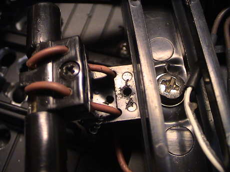
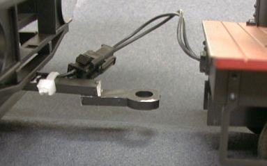
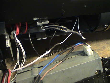
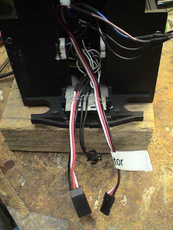
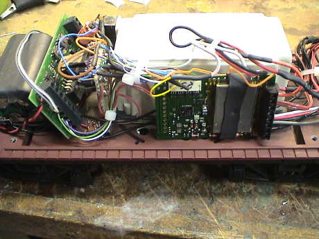
The harness to the left is the one going to the Sierra lighting outputs. The two black wires in the middle are the Aristo supplied track power jumper. The harness on the right goes to the decoder and carries the motor and headlight wires. Those two three wire harnesses are actually the same part, but reversed so that they cannot be cross connected.
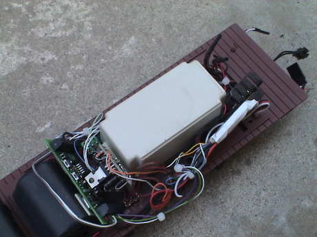 The tender was
rearranged somewhat. I found during fit checks that with the Sierra
sitting on top of the battery, it was actually interfering with the
tender roof and putting the stack in compression. I had to fix that so
the Sierra was moved to the sloping front side of the battery sitting
crosswise. It is retained by a piece of foam tape.
The tender was
rearranged somewhat. I found during fit checks that with the Sierra
sitting on top of the battery, it was actually interfering with the
tender roof and putting the stack in compression. I had to fix that so
the Sierra was moved to the sloping front side of the battery sitting
crosswise. It is retained by a piece of foam tape.
The interface board containing the battery charger and the opto isolators was mounted on the back of the speaker box, also with foam tape, facing the Sierra. The decoder is sitting alongside of the speaker. There is room there for the DG583S when it eventually arrives, but the DG580L that I installed to allow me to test the rest of the installation is working fine with hardly any motor noise at all. It may have found a permanent home. The DG583S can go somewhere else.
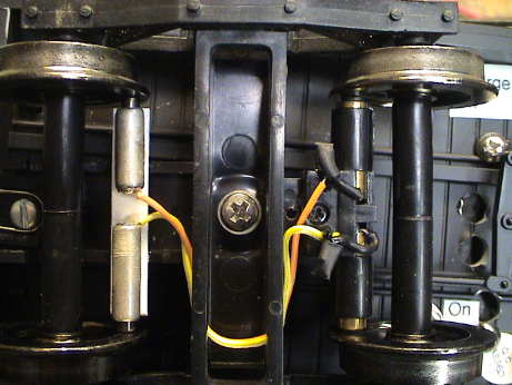
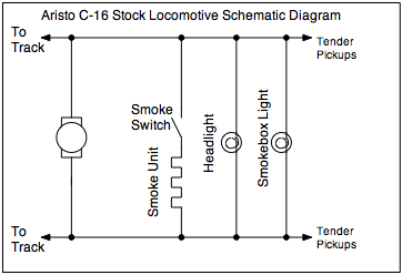 As far as I can
tell without pulling out the switch board, this is how this
pre-production C-16 is wired. I strongly suspect that the early
production units are different and that later production units are
different yet.
As far as I can
tell without pulling out the switch board, this is how this
pre-production C-16 is wired. I strongly suspect that the early
production units are different and that later production units are
different yet.
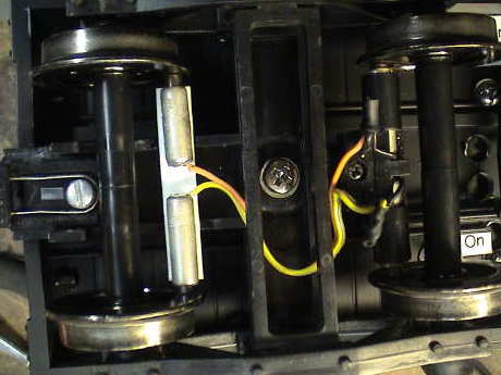
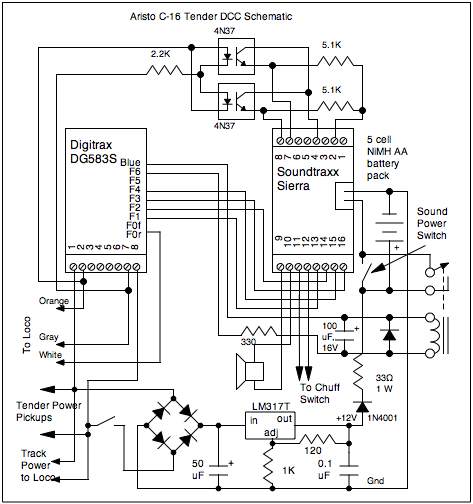
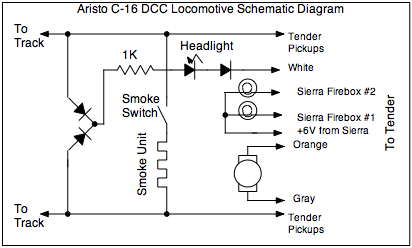 After I
was done with it, this is how the loco is wired. The only part that is
actually the same is the smoke switch and power pickup wiring.
After I
was done with it, this is how the loco is wired. The only part that is
actually the same is the smoke switch and power pickup wiring.
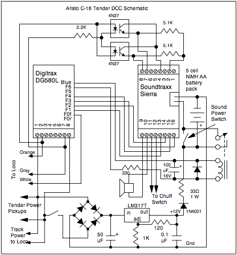 There
was noting in the original tender except the power pickup wiring. I
have added everything else. All this stuff is, based on my experience,
necessary to make a Sierra work properly with DCC.
There
was noting in the original tender except the power pickup wiring. I
have added everything else. All this stuff is, based on my experience,
necessary to make a Sierra work properly with DCC.
I did add a relay derived from a function output of the decoder. The relay is just a 2nd power switch that allows the sound system to be enabled and disabled with the decoder. Upon loss of track power, the relay will relax as well and shut the sound system off. I was often forgetting to turn off the sound system. This particular relay has a 12 volt coil so the 330 ohm resistor is there to drop the coil voltage to 12 volts for this particular relay.
The 100µF capacitor across the relay coil is to prevent chattering during short power dropouts. With this capacitor in place, SOME sort of resistor is needed between the relay and the function wire. The peak current of the capacitor charging could blow out the function control transistor in the decoder without a small resistor. 100 ohms should be sufficient to limit the charging current even if a resistor is not needed to drop the coil voltage.
When I finally got the C-16 back to the Mtn Div, I put it on the track and did a test run. The results were less than adequate. The motor block was making quite a bit of gear noise that I hadn't noticed outdoors, but on the indoor layout the noise was bothersome. Further, the thing got only 1/3 the way around and stopped. Actually, it didn't completely stop, it was just moving slowly forward and not responding to commands. This is what happened to another DG580L when it died some years ago. After a little more messing around, the thing just stopped completely. The motor controller was dead.
Earlier in the day I had swapped out another DG580L from the Lionel Handcar for a DH123 which worked quite a bit better. I pulled the dead decoder and swapped in that one back in the C-16. The loco ran then, but it still made some gear noise, worse going forward. It didn't draw a lot of current, between a half and one amp, but it sounded like it needed lubrication, or at least inspection to see what was going on. Once the brick is removed from the loco, the worm that drives the front axle can be lubricated from the top of the block. The spur gears that drive the worm shaft can be lubricated via a small port on the left rear of the brick. However, the worm that drives the rear axle cannot be accessed from the outside.
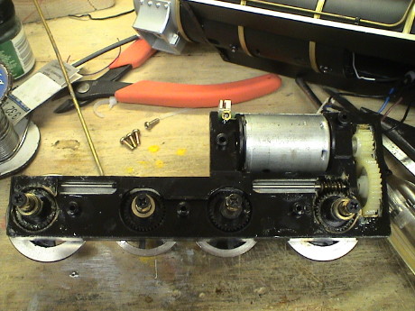 Getting to the gearing
required disassembly of the brick. To do this, the wheels need to be
removed from the left side. This could be done with the connecting rod
in place, but it easier to remove it. Then the wheels need to come off.
Once the screws that holds a wheel on is removed, the wheel itself can
be gently pried off the axle with a flat blade screwdriver. Then 4
screws need to be removed from the left side and the left part of the
block will lift off. At this point, the whole gear train is accessible
for lubrication. If you have to isolate the motor connections, the
right side will need to come off too.
Getting to the gearing
required disassembly of the brick. To do this, the wheels need to be
removed from the left side. This could be done with the connecting rod
in place, but it easier to remove it. Then the wheels need to come off.
Once the screws that holds a wheel on is removed, the wheel itself can
be gently pried off the axle with a flat blade screwdriver. Then 4
screws need to be removed from the left side and the left part of the
block will lift off. At this point, the whole gear train is accessible
for lubrication. If you have to isolate the motor connections, the
right side will need to come off too.
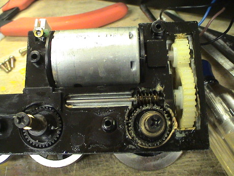 This is the detail of
the motor, it's gearing and the rear driver worm. After lubrication, it
didn't make as much noise as before, but it was still pretty noisy.
Spur gears tend to be noisy. This may be why the newer C-16's have a
belt drive in place of the spur gears.
This is the detail of
the motor, it's gearing and the rear driver worm. After lubrication, it
didn't make as much noise as before, but it was still pretty noisy.
Spur gears tend to be noisy. This may be why the newer C-16's have a
belt drive in place of the spur gears.
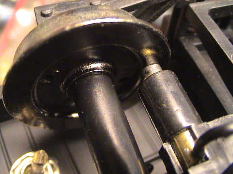
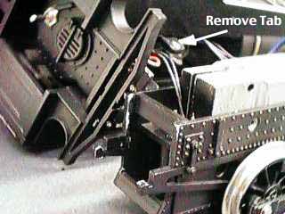
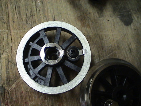 I also had a problem
with continuity of the 3rd driver on the right side. This hadn't
changed since the loco was new, but since the blind drivers rarely
touch the track anyway, I had never bothered to dig in and fix it. I
took the wheel off and found that the tab that is supposed to touch the
rim was not making contact. The contact was removed, cleaned, bent a
little and reinstalled and then it worked.
I also had a problem
with continuity of the 3rd driver on the right side. This hadn't
changed since the loco was new, but since the blind drivers rarely
touch the track anyway, I had never bothered to dig in and fix it. I
took the wheel off and found that the tab that is supposed to touch the
rim was not making contact. The contact was removed, cleaned, bent a
little and reinstalled and then it worked.
After I got the loco all back together after the lube job, I gave it another test run but it didn't get far as the right crosshead assembly wasn't assembled properly and it jammed. The 2nd decoder never recovered from the stall. It was dead. Since that was the last live DG580L that I had, I'll never be cursed by these things again. When a DG583S arrives, it'll go in this loco and I don't expect to have any more problems.
 Eventually, Digitrax
shipped the DG583S and it got installed in the C-16 the day that it
arrived. It fit nicely right where the DG580L was. Digitrax also has
not changed the wiring of the 9 pin function connector in all those
years, so the function connector plugged right into the function
connector on the DG583S. The track and motor wires were simply cut off
the DG580L and connected to the appropriate screw terminals on the
DG583S.
Eventually, Digitrax
shipped the DG583S and it got installed in the C-16 the day that it
arrived. It fit nicely right where the DG580L was. Digitrax also has
not changed the wiring of the 9 pin function connector in all those
years, so the function connector plugged right into the function
connector on the DG583S. The track and motor wires were simply cut off
the DG580L and connected to the appropriate screw terminals on the
DG583S.
 There was one complication
however. There is a "bug" in the DG583S where the white (front
headlight, F0f) wire and the yellow (rear headlight, F0r) wire are
reversed. I did have to reconnect the headlight wire leading to the
engine from the decoder white wire to the yellow wire. Other than that,
it all worked very well. CV49 still controls the attributes of the
front headlight like it is supposed to.
There was one complication
however. There is a "bug" in the DG583S where the white (front
headlight, F0f) wire and the yellow (rear headlight, F0r) wire are
reversed. I did have to reconnect the headlight wire leading to the
engine from the decoder white wire to the yellow wire. Other than that,
it all worked very well. CV49 still controls the attributes of the
front headlight like it is supposed to.
This page has been accessed times since 21 Aug 1998.
© 1998-2008 George Schreyer
Created 21 Aug 1998
Last Updated December 18, 2008